Remember the auto-fire (turbo) button on old video game controllers? This project adds an auto-fire button to a mouse for use with video games or just clicking random things quickly (if thats what you're in to) using no more than a 555 timer, a capacitor and a couple resistors. My goal was to create it as cheaply as possible and without interfering with the normal functionality of the mouse.
Parts List
I wanted to accomplish my goal and keep it as simple as possible. The entire thing consists of very few components and comes in under $3 total. (priced per item on sparkfun… actually it was free since I had the components laying around)
- 555 timer
- 1k Resistor
- 10k Resistor
- 10uf Capacitor
- push button
- couple inches of wire
- about a square inch of protoboard
Connecting to the mouse PCB
First we crack open the mouse. I'm not going to cover that here since it'll be different with every mouse. For mine it was one screw then pull the top and bottom apart until you feel like it's going to break and it unclipped. This might not be how your mouse is held together so don't blame me if you break it in half trying to force it.
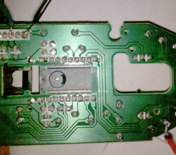
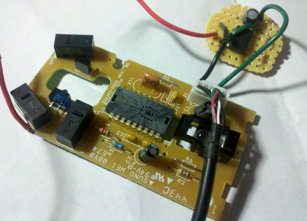
Once I got inside I used a multi-meter to find a good 5v+, gnd, and a pin to control the mouse clicks. Then just soldered a wire to each pin as shown. Black = GND, Green = 5v+, Red = Left Click Control wire.
Creating the prototype
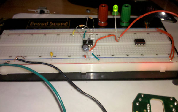
It's been a while since I've played with 555 timers so first I did a prototype on a breadboard. I included an LED to show that I could make the LED flash using the mouses power then just connected the output (pin 3) from the 555 to the control wire that I ran from the mouse PCB previously.
Schematic
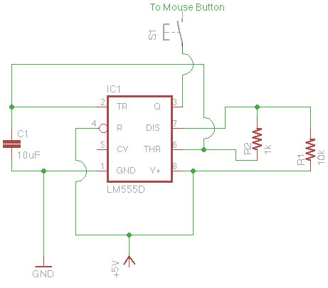
Next I put together a schematic of the system. The whole thing is just a 555 timer, a 10uF capacitor, a 1k Resistor, and a 10k resistor. The speed can be adjusted by changing the resistors. These are what I happened to have on hand. Also, I noticed if I made the autofire any faster the computer couldn't keep up with the clicks.
Creating the circuit board
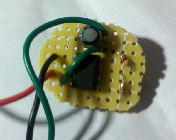
I put it together with some protoboard. It could've probably been done as a "dead bug" circuit, but I prefer to keep things a little bit neater. Plus I was afraid of things moving around inside of the mouse and causing a short.
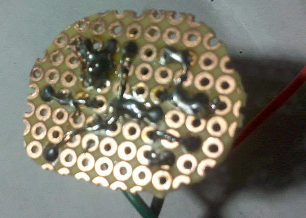
and the back all soldered together. It's not the neatest job, but it gets it done.
Connecting it to the mouse
Once everything was laid out on the board I just had to connect the 3 wires I connected to the mouse PCB earlier and give it a test. Guess what? It worked great ![]()
Putting the mouse back together
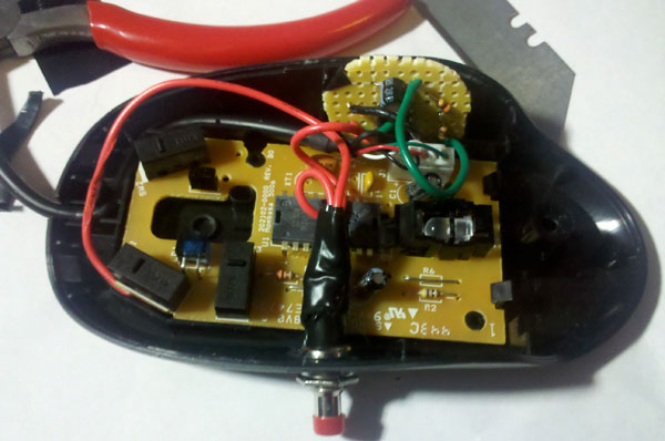
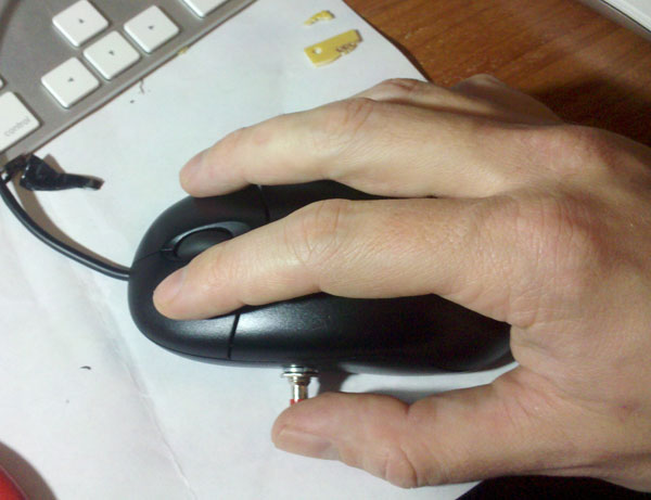
First I carefully drilled a hole in the side of the mouse to ensure the push button was in a convenient position to push with my thumb. Also, I had to make sure it cleared the mouse PCB on the inside. Then I took some snips and a razor blade and trimmed back some of the plastic parts inside the mouse to create a spot for the auto-fire circuit to fit.
All done!!
Then I just had to put the top of the mouse back on. Which was quite a task. I had to stop and carve out more plastic from the supports in the top to make room for the new circuit, but after a bit of cutting and squeezing it all fit back together and outside of the red button sticking out of the side you'd never know anything was done to it.
Testing time
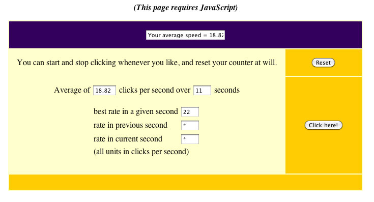
All of the normal mouse features work great: clicking (left / right), scrolling, middle click, etc. To test out the autofire I just went to google and typed in "clicks per second" and clicked on the first link. Actually I did this the first time with the prototype on the breadboard. Then went back once it was all put together and this time I took a screen shot to show my click rate using the autofire button.

Steven
December 27, 2010 at 1:56 pm
Really cool hack. Simple, cheap, and well documented. Keep up the good work!!
Robert
December 27, 2010 at 1:57 pm
It’d be really cool if you added a switch to select between left and right mouse button
Michael
February 1, 2011 at 4:55 pm
Groovy.
Doing this to both buttons with some maxim samples.
IT”S YOUR FAULT, Lenny!!